 AUTHORIZED JEKKO DEALER
 AUTHORIZED HYRAX DEALER
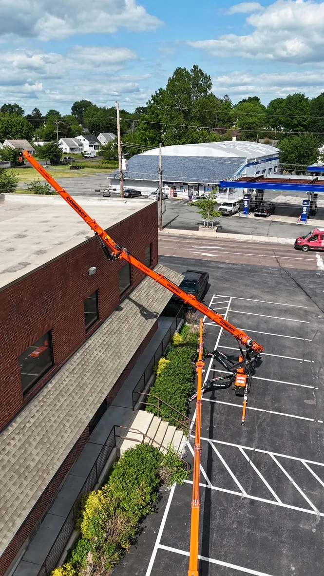
On Jekko models with J-level chart selection, the remote shows a stability level for the current setup and working sector. The label identifies the chart the machine is using. It does not describe a universal leg position or guarantee the same capacity on another model.
01What a J-zone is
A J-zone, or stability level, is Jekko's label for the applicable stability condition. The levels and charts available depend on the SPX model, revision and configuration. Each chart is a separate rating table. A higher level does not make the headline capacity available at every radius, and a chart for one model cannot be substituted for another.
The important word is separate. A J4 chart is not the J7 chart with a percentage knocked off. Jekko calculates each one from the actual geometry of that footprint, and the crane's load moment indicator loads the matching table and stops boom motion at its limits. There is no operator setting for the level. The crane measures it.
02The ladder: J0 to J7
03How the crane picks the level
The stability system reads the swing angle and extension of all four outriggers and knows, from its own geometry, exactly where each pad sits relative to the slew center. It connects adjacent pads to form the support polygon and draws a tipping line between each neighboring pair. Then it measures one number: the perpendicular distance, call it d, from the slew center to the tipping line the boom is currently working over.
The distance is compared with the model-specific thresholds. The referenced SPX532.2 sheet maps d of 7 ft 6 in to J7, 6 ft 11 in to J6, 6 ft 2 in to J5, 5 ft 1 in to J4, 3 ft 9 in to J3, and 2 ft 4 in to J2. Conditions outside those stabilized levels require the separate restrictions identified by the manufacturer; do not assume they permit a lift.
Why it is distance, not spread
Two setups with the same total width can land in different zones. Swinging a leg wide but leaving it short can put the pad in a spot that does not help the tipping line the boom is working over. The system does not care how the footprint looks; it cares how far the slew center is from the edge it could tip over. That is also why the rule of thumb "half out equals half capacity" is wrong on a Jekko. The chart is chosen by geometry, and the geometry is measured, not assumed.
04Same letters, different numbers
The level labels are shared across the referenced sheets, but the thresholds and available charts differ by model and configuration. Never transfer a threshold between machines or treat a J5 chart for the SPX650 as a J5 chart for the SPX532.2.
| Model | J2 | J3 | J4 | J5 | J6 | J7 |
|---|---|---|---|---|---|---|
| SPX328EVO (EVO kit) | 2′ 5″ | 3′ 4″ | 3′ 9″ | 4′ 4″ | 4′ 11″ | 6′ 1″ |
| SPX328EVO (standard) | - | - | - | 3′ 4″ | 5′ 1″ | 6′ 1″ |
| SPX532.2 | 2′ 4″ | 3′ 9″ | 5′ 1″ | 6′ 2″ | 6′ 11″ | 7′ 6″ |
| SPX650 | 3′ 7″ | 4′ 5″ | 5′ 6″ | 6′ 1″ | 7′ 3″ | 8′ 6″ |
| SPX1280 (full counterweight) | - | - | 4′ 5″ | 5′ 4″ | 6′ 1″ | 7′ 5″ |
| SPX1280 (no counterweight) | 4′ 5″ | 5′ 4″ | 6′ 1″ | 7′ 5″ | - | - |
Minimum tipping-line distance d for each level, from the named technical data sheets below. The base SPX328 CL carries J5 to J7 stabilized charts; its EVO-KIT uses a different mapping with J2 to J7. The SPX1280 maps the same physical thresholds differently with and without counterweight. A dash means that level is not shown for that configuration.
These tables must be read with their model and configuration notes. Counterweight configuration changes the SPX1280 chart selection, and the SPX328 base and EVO-KIT charts use different mappings. Check the manufacturer's stability examples and the crane display for the actual setup rather than assuming a level from a familiar footprint.
05One setup, several zones
Because d is measured to the tipping line the boom is working over, the level is directional. An asymmetric footprint, wide on one side and tucked on the other, is not "a J5 setup." It is J7 over the wide side, J5 or J4 over the tight side, and the crane switches charts as the boom slews across the boundary. The remote display updates as the boom rotates, and the LMI enforces whichever chart applies to the sector the boom is in right now.
The manufacturer's stability examples show that a single footprint can divide the slew circle into different rated sectors. Changing leg angles or extensions changes those sectors. A compact arrangement may also include sectors where lifting is not permitted. The plan must account for every chart and restriction along the load path, not just the strongest side of the crane.
06Reading the chart for your zone
- Identify the model, the manual revision, and the boom or jib configuration. Charts are specific to all three.
- Read the J-level off the display after every leg is locked and the crane is level. Do not estimate it from the placard.
- If the lift slews through more than one sector, note the lowest level on the path. That is the chart that governs.
- Open that J table. Find the row for the working radius (round up to the next listed radius if between rows) and the column for the boom length.
- Subtract hook block, rigging, and any attachment weight unless the chart notes they are included.
- Compare the net to the load. If the answer is no, the fix is more footprint on the weak side, a shorter radius, or a different machine, never a different chart.
07What it means in the field
- The number on the screen is a chart selection, not a warning. J5 is a fully rated condition with its own table.
- Set up for the lift, not for the maximum. If J5 covers the pick with margin, the tight footprint is the right footprint.
- Plan around the weakest sector the load crosses, because that is what the LMI will hold you to.
- Never transfer thresholds or tables between models, revisions, or counterweight configurations.
- Every pad grounded and every leg locked is what turns the intended J into the actual J.
- Bring the footprint, the level, and the pad reactions to the site meeting. Reviewers approve numbers, not intentions.
CLE can help review the applicable Jekko chart and revision for the proposed machine before delivery. Send the setup area, configuration and load so the footprint and working sectors can be checked. Confirm the final setup and chart selection on the machine before lifting.
Manufacturer sources and configuration notes
Jekko SPX328 CL 5950 lb TD REV3.2, 19 January 2026, p 6 (transport width, height and headline capacity); pp 13 and 32 (base and EVO-KIT stability selection).
Jekko SPX532.2 TD REV0.4, 24 September 2025, p 9 (CL-2 dimensions and headline capacity); p 16 (stability selection).
Jekko SPX650 TD REV2.0, 9 May 2025, p 9 (CL-2 dimensions and headline capacity); p 16 (stability selection). CLE unit variant and later revision remain to be confirmed.
Jekko SPX1280 TD Rev.8, 19 January 2023, p 5 (CL3 dimensions and headline capacity); p 9 (counterweight-dependent stability selection).